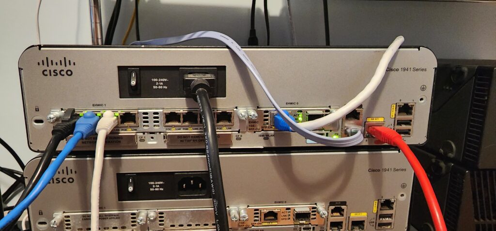
In my last blog post, I described the process of configuring Inter-VLAN Routing and one of the pieces of hardware in my topology was a Cisco 1941 Series Gen 2 ISR Router with an 8 port Switch module. To be more accurate this 8 port switch module is called an 8 port Gigabit “Ethernet Enhanced High-Speed WAN Interface Card” (EHWIC). Try saying that 5 times super fast! Here is a picture of my router with the switch module:
What is an EHWIC?
The Product Overview in the EHWIC datasheet probably says it best:
“The 4- and 8-port Cisco® Gigabit Ethernet Enhanced High-Speed WAN interface cards (EHWICs) can reduce your company’s total cost of ownership (TCO) by integrating Gigabit Ethernet (GE) switch ports within Cisco 3900, 2900, and 1900 Series Integrated Services Routers (ISRs). These low-density Gigabit Ethernet switches offer small to medium-sized business (SMB) and enterprise branch-office customers a combination of switching and routing integrated into a single device….
Integration of these switches with Cisco IOS® Software allows network administrators to manage a single device using Cisco management tools or the router command-line interface (CLI) for LAN and WAN management needs. This approach reduces network complexity, lowers maintenance contract costs, and lessens staff training needs. It also simplifies software qualification efforts and delivers a consistent user experience at branch offices…
The 4- and 8-port Gigabit Ethernet EHWICs provide line-rate Layer 2 switching across onboard Gigabit Ethernet ports. The 4-port Gigabit Ethernet EHWIC has four 10/100/1000 switch ports, with options for PoE support on all four ports. The 8-port Gigabit Ethernet EHWIC has eight 10/100/1000 switched Gigabit Ethernet ports, with a PoE support option on all 8 ports…”
It sounds to me from this product overview that this product was meant to simplify the deployment and management of a network for a small to medium sized business. To implement a single device and integrate switching and routing similar to the many SOHO routers you will find at your local best buy, the difference being is that you get a certain degree of enterprise features. Speaking of features, there is one feature missing from this EHWIC that is just so disappointing – support for 802.3ad/802.1ax or Static LAG/LACP. This is actually the reason why I was compelled to find the data sheet; in order to confirm support for LAG. I was wanting to issue the channel-group command so that I can create a L2 etherchannel and the command wasn’t available. Although this EHWIC is a L2 device, it clearly is not a fully featured L2 device.
My Previous Attempt to Configure The EHWIC
I bought the EHWIC early in my CCNA journey when I was still growing my understanding of how Layer 2 and Layer 3 devices work. I initially thought that I would be able to configure some ports on the EHWIC as L3 routed ports, similar to what you can do on a multilayer switch. I was very wrong about this since this EHWIC only operates at layer 2 so I was left with a piece of hardware that I really didn’t understand how to use or what was its purpose. (I didn’t read the datasheet initially)
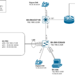
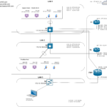
As I am hammering away at my next project, something just didn’t sit well with me about the topology of my last blog post. For review here is the network diagram:
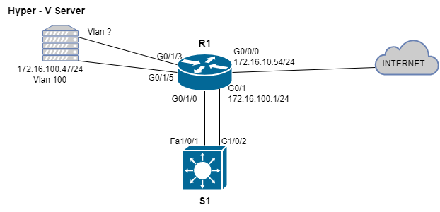
I mentioned that I needed the Layer 3 switch (S1) in order for the end hosts in different VLANs connected to the EHWIC to be able to communicate with each other and reach the internet. My rationale was that the EHWIC is a L2 device and it needs a router to route between VLANs and reach networks outside of the LAN. I have not revisited this since I first attempted to configure Inter-VLAN routing with this EHWIC a while back when I bought it. What I tried to do was connect one of the L3 ports on R1 to one of the L2 switchports on the EHWIC. After connecting the ports, I tried to configure a VLAN and subnet on the L3 port on R1 and then configure that same subnet and VLAN on the EHWIC and I got the following result:
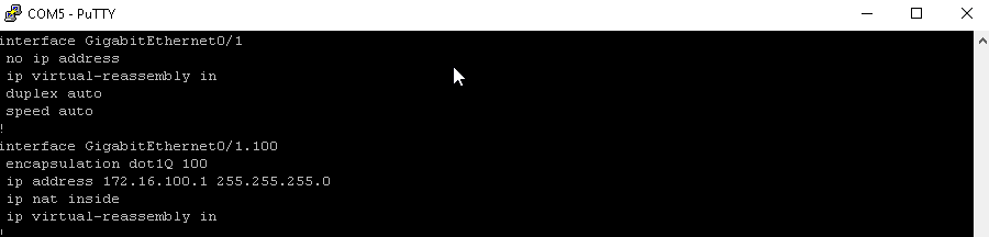
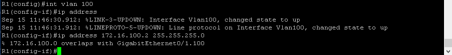
Now why wasn’t I able to configure this IP address to VLAN 100 on R1? Its because I assigned g0/1.100 the address space 172.16.100.0/24 and 172.16.100.2 is in the address space I assigned to this sub-interface (g0/1.100). You cant assign multiple interfaces to overlapping subnets. However after revisiting this I discovered that what I was trying to do was unnecessary and inefficient as I was wasting one of the ports on the switch module. Also, there was no reason for me to give VLAN 100 an IP address. Ultimately what I was trying to accomplish was for the end hosts connected to the switch module to communicate with the internet but all I needed to do was configure Network Address Translation (NAT).
What is Network Address Translation (NAT) ?
NAT or Network Address translation is the reason why our devices at home are able to communicate with the internet. Routers use NAT in order to translate a “private” IP address into a “public” IP address which can be used to route traffic across the internet. Private IP addresses like 192.168.0.1, 172.16.0.1 or 10.0.0.1 cannot be used to communicate with resources across the internet because they are reserved. There are only so many usable IPv4 addresses and NAT is the final life line that has kept IPv4 alive this long.
Solving the Mystery
So how the heck should I use this EHWIC? How do I get rid of this extra switch (S1), and collapse routing and switching into one device? To accomplish this I issued the following commands on R1:
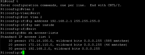
I created VLAN 2 and then assigned the IP address 192.168.2.1 with a /24 subnet mask to the VLAN 2 interface. This IP address will be the default gateway for the end hosts connected to this VLAN. Then I issued the “ip nat inside” command to specify what cisco calls in IOS the “inside local” network or simply the network assigned to a private IP address space. The internet side of NAT is already configured. R1’s g0/0/0 is configured with the “ip nat outside “command to specify the outside part of the network or the network that is able to communicate with the internet. Since this is a lab environment I have a private IP address assigned to this interface. Finally, I created another entry in the existing ACL to allow the traffic coming from the 192.168.2.0/24 subnet to be translated. The show access-lists command shows the new entry (entry 30).
To test connectivity, I used 2 windows 10 computers. One in VLAN 2 and the other in VLAN 3:
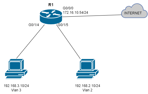
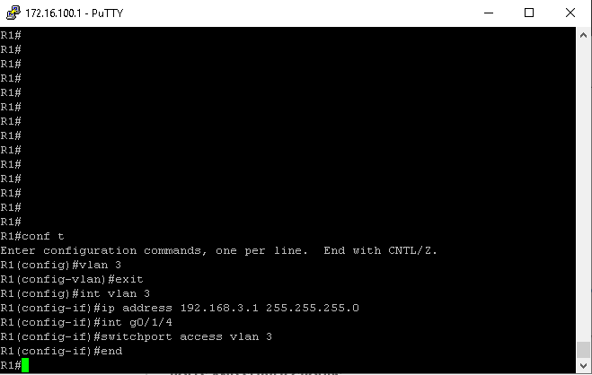
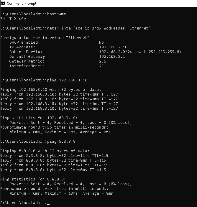
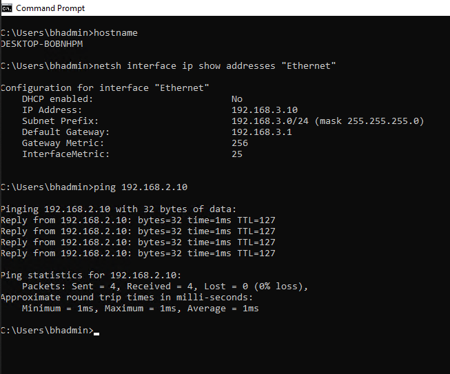
I created VLAN 3 on R1, assigned it the subnet 192.168.3.0/24 and then gave R1’s g0/1/4 interface access to VLAN 3. I didn’t bother adding VLAN 3’s subnet to the ACL on R1 since I will already be demonstrating internet access on the PC connected to VLAN 2. Figure 1-7 shows successful pings to the end host in VLAN 3 as well as to Google’s public DNS servers. Figure 1-8 shows successful pings to the end host in VLAN 2.