In my blog entitled “Inter-VLAN Routing Between Virtual Machines” I created two subnets and made the necessary configuration on the router and in Hyper-V Manager to communicate between hosts in two different VLANs. The configuration works great but there is one glaring limitation – scalability. If I wanted to add more VLANs and assign those VLANs to a subnet, I would need to add more NICs. To address this limitation, I will configure a NIC Team in Windows Server 2019 and specify in Hyper-V Manager what VLAN I want my VMs to use for network communication.
A NIC Team is a way to group together several physical interfaces into one logical interface for the purpose of improving network performance and redundancy. In Cisco IOS this is also called an EtherChannel.
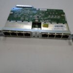
For this task I purchased an Intel Pro 1000 PT 1Gb Quad Port Ethernet Server Adapter. My hope was that I would be able to put all the ports in a Team or create two Teams with two ports in each team but this computer is only able to see two of the 4 ports on the server adapter. After troubleshooting for a few hours I could not figure out why my computer is unable to see all the ports. Perhaps there is some kind of hardware limitation unique to the Dell Optiplex 7010. I decided to power through and just use the two ports I am able to use.
VLAN Aware vs VLAN Capable
One of the things that came up for me as I was accomplishing this task is distinguishing the difference between VLAN Awareness and VLAN Capability. In the Hyper-V Virtual Switch Manager you are given the option of specifying a VLAN however when using this, you are not actually creating a VLAN. VLANs are created on the port of the network switch (VLAN capable). However, what Windows Server 2019 can do is acknowledge that a packet is tagged with a specific VLAN and pass the traffic to the switch to make the appropriate forwarding decision (VLAN aware). This is great because typically computers drop packets that are tagged with a VLAN.
NIC Team Configuration
To create a NIC Team, open the Server Manager and with “Local Server” selected in the left navigation pane, select the NIC Teaming option under the server properties. Then select “Tasks” under the “Teams” section and you will be able to select the interfaces you would like to join your new NIC Team, the Teaming mode and the Load balancing mode. In figure 1-1 I have right clicked on the NIC Team I created and selected properties which is identical to the screen you see when creating a new NIC Team:
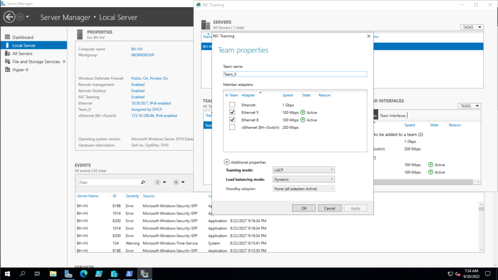
LACP or Link Aggregation Control Protocol allows the switch to dynamically negotiate which links between the switch and the host get added to the Link Aggregation Group (LAG). LACP in Windows Server operates in “active mode” so that means that on the switch I will also need to configure LACP in active mode. Im not overly concerned about load balancing performance so for the load balancing algorithm I went with Dynamic.
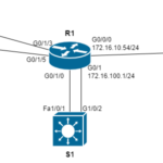
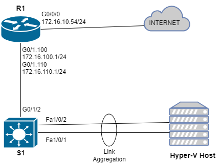
For this task I have also slightly amended the topology from my blog entitled “Inter-VLAN Routing Between Virtual Machines.” Since the EHWIC in my router does not support Link Aggregation, I will add a multilayer switch:
EtherChannel Configuration
Below are the commands issued on S1 to configure a L2 EtherChannel:
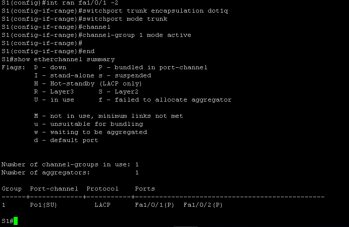
It is important first to make sure that both ports on the switch have the same configuration before creating the EtherChannel. I issued the #interface range command and grabbed both the fa1/0/1 and fa1/0/2 interface, configured the encapsulation protocol and set both to trunk mode. Then I created the etherchannel by issuing the #channel-group command and configured the negotiation protocol as “active” to specify to the switch that I want it to use LACP. Finally, I issued the #show etherchannel summary command to show that etherchannel is in an “up” state.
Confusingly, Cisco uses “etherchannel” , “channel group” , and “port channel” all to refer to the same thing. The output of this show command shows that I created a new logical interface called “Po1” and the protocol being used is LACP. The letters “S” and “U” are in parenthesis which according to the key in the show command output, indicate that this new logical interface is in use and is operating in L2. Success! The last thing to do now is specify in the Hyper-V Manager which VLANs I want to be used for network communication for the VLANs:
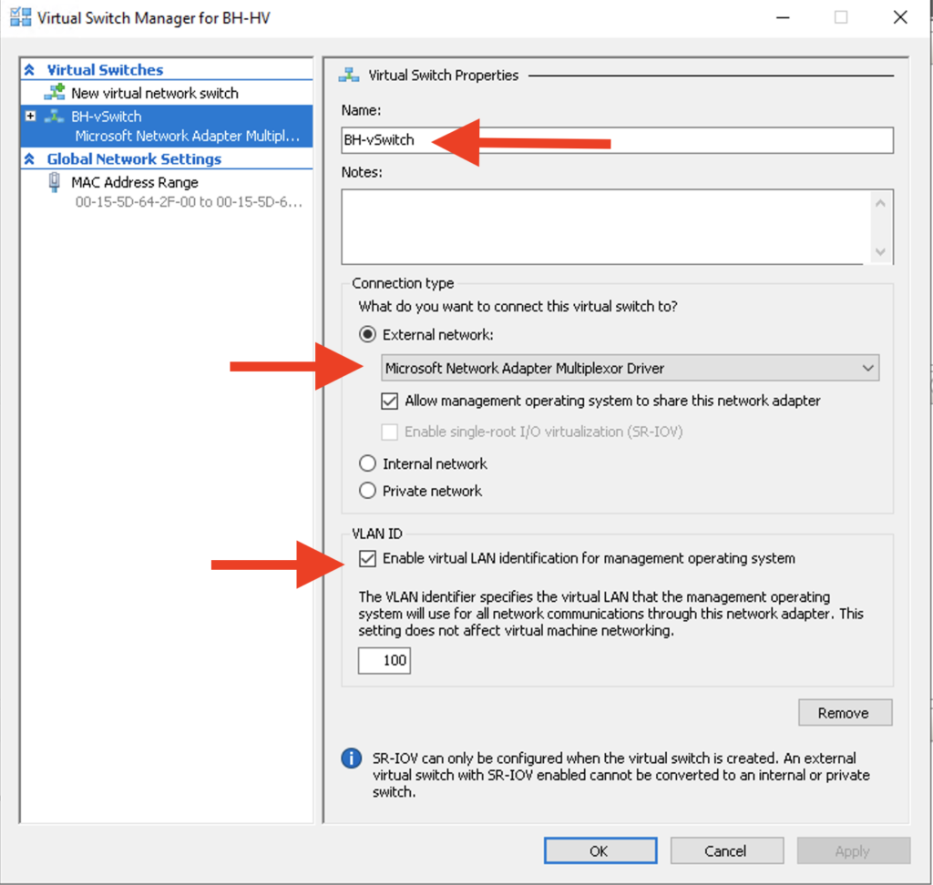
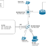
First I selected the Virtual Switch Manager and renamed my vSwitch. Then I chose the NIC Team which is represented as “Microsoft Network Adapter Multiplexor Driver” and binded this NIC Team to the External vSwitch. I want the Hyper-V Host to participate in this vSwitch so I also selected the option “Allow management operating system to share this network adapter” The final piece of configuration for this external vSwitch is to specify VLAN 100 as the VLAN I want the Hyper-V host to use to communicate on the network.
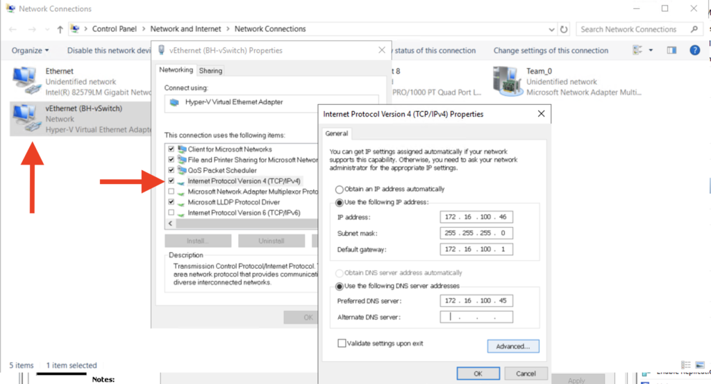
Next I needed to configure a static IP address to the virtual NIC:
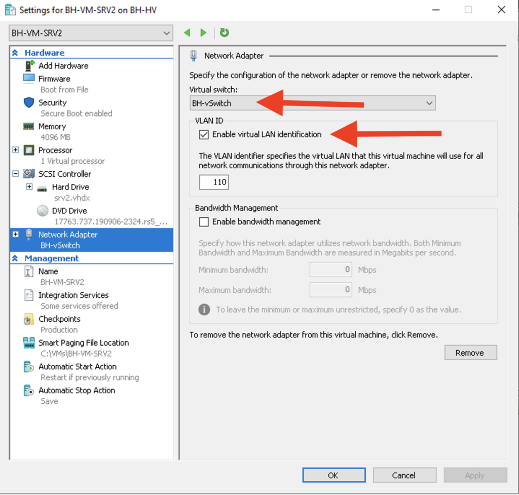
The last piece of Hyper-V config is assigning each VM to the external switch “BH-vSwitch” and specifying the VLAN that I want each VM to use for network communication. BH-VM-SRV1 will be use VLAN 100 and BH-VM-SRV2 will use VLAN 110:

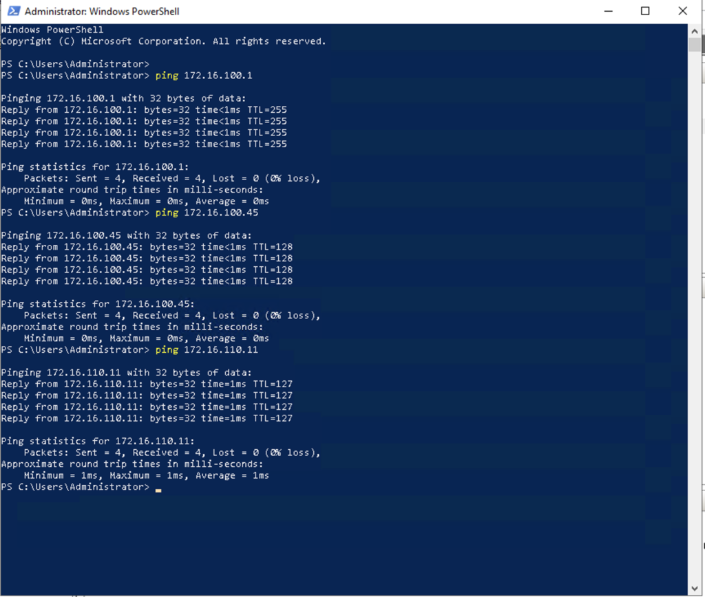
All that’s left is to test connectivity! From the Hyper-V host I was able to successfully ping the gateway of VLAN 100 as well as each VM as shown in figure 1-7 below. I was also able to successfully ping BH-VM-SRV1 from BH-VM-SRV2 and vice-versa.