Lately I have done a really good job at trying to document the fun I have in my home lab environment. My goal is to post a blog on my site at least once a week. However, in the past couple weeks I decided to increase the complexity of the network I have been building out in my home lab and because of that I been doing a lot of troubleshooting. I am happy to say that I got everything working the way I wanted it to work though. A few times during the past couple weeks I struggled to figure out why certain things weren’t working in my network and I had to step away until the next morning a few times. I always find it amazing that the answer to my problem the day before would stare it me straight in my face after returning back to it!
My Objective For This Lab
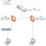
My objective for this lab is to add a few more LANs, some routers and configure a single area OSPF instance. One of the routers I will use is actually a desktop pc that has pfSense installed. I am curious about how OSPF is implemented in pfSense and wonder how straight forward it would be to make my pfSense box a neighbor in my network running OSPF. Here is my topology:
What is Dynamic Routing and OSPFv2?
The way in which end hosts in a Local Area Network are able to communicate with other end hosts in a remote LAN is by utilizing layer 3 of the OSI model. Routers operate at Layer 3 and is responsible for routing traffic between LANs. How do routers do this? Routers have a table of routes to other networks stored locally in memory. When a router receives a packet, it looks at the destination IP address in the packet and tries to match it with the most specific route (route with the longest prefix length). How do these routes get into the routing table?
In simple networks with just a handful of routers, configuring a static route manually on each router would work fine. However as networks grow in size and complexity, manually configuring each route to every network increases the likelihood that human errors would be made in adding all the routes. Also if for some reason a link in the topology goes down and there is a static route configured to route across that link, the router will continue to choose that route even though it is down. This spells trouble for larger more complex networks and using dynamic routing protocols addresses these short comings of using static routing.
Dynamic routing is the way that routers are able to share routes with other routers. The way routers do this is by using dynamic routing protocols and one really awesome dynamic routing protocol is OSPFv2. As a side note, OSPFv2 is used mostly to configure IPv4 networks and OSPFv3 is used for IPv6 networks. Since I am using an IPv4 network, for the purpose of this blog I will refer to OSPFv2 as simply OSPF. OSPF is a link-state dynamic routing protocol. This means that all routers using a dynamic routing protocol like OSPF create a ‘connectivity map’ of the network and advertises information about the subnets that it knows to all other routers until all routers have the same map of the network. OSPF not only gives routers the process for sharing routes with other routers but it also gives routers the process for choosing the best route for each destination. Dynamic routing protocols use a metric to choose the best route to a destination. OSPF uses the metric of cost to choose the best route to a destination. OSPF cost is calculated by dividing the bandwidth by the link speed. There is so much more to say about OSPF but my goal here is to provide a quick high level view of routing protocols and OSPF specifically.
How do routers become OSPF neighbors?
Essential to OSPF are neighbor relationships. OSPF neighbors are routers running the OSPF process and are connected to the same subnet. When these two conditions are met, they can exchange OSPF messages so that they can agree to become neighbors and share network routes. Additionally, OSPF allows for the dynamic discovery of other routers running OSPF; all that is needed is for the routers to be on the same subnet.
I wish that I could just list all the steps I took chronologically to get OSPF up and running but the truth of the matter is that the path to get there was messy. I did however have a list that helped me get back on track after running into issues that I needed to address. When I was preparing for CCNA, I used Jeremy’s IT Lab CCNA course on YouTube and in reviewing OSPF for this blog post, I leaned on this list to guide my thinking behind configuring OSPF in this network:
OSPF Neighbor Requirements:
- OSPF Router IDs must be unique
- Area number must match
- Interfaces must be in the same subnet
- OSPF process must not be shutdown
- Hello and Dead timers must match
- OSPF Network Types must match
- Authentication settings must match
- IP MTU settings must match
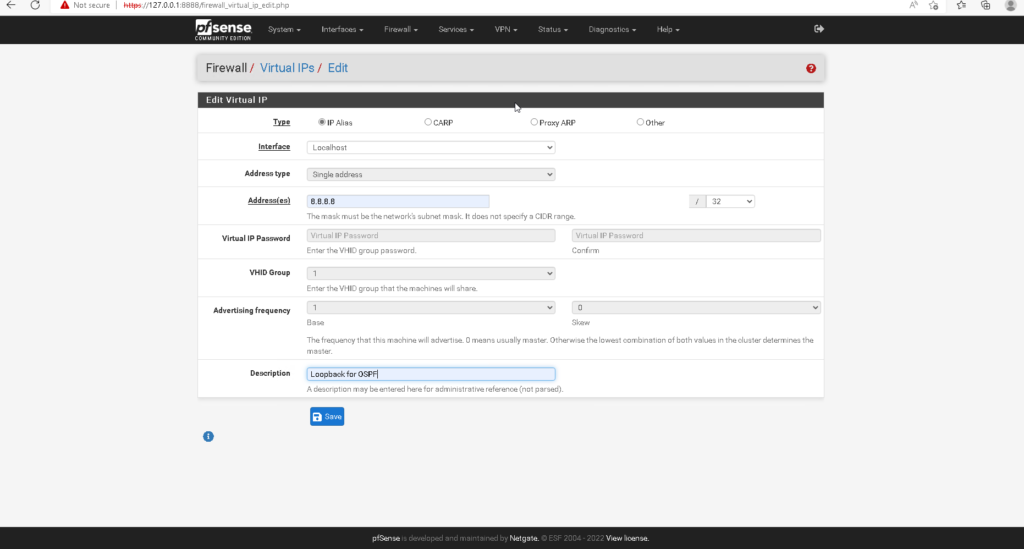
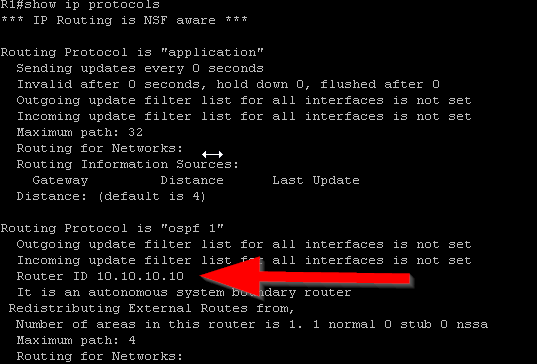
The first requirement is ensuring that each router has a unique router ID. OSPF uses the router ID to identify OSPF neighbors. On a cisco router, OSPF chooses its router ID within a certain priority. If the router ID is manually configured then it chooses that first. If there is no manually configured router ID, then it chooses the highest numerical loopback interface configured on the router. If there is no loopback interface configured then the router chooses the highest numerical IP address assigned to an interface. I chose to configure loopback interfaces on each router. Loopback interfaces are great because they will always be in an “up” state. This is useful in the event that when any of the links on a router fails or goes down for any reason, OSPF still has an interface to send OSPF messages to. After you configure the loopback interface and enable OSPF, you can verify that the router has chosen the loopback interface as the router ID by issuing #show ip protocols command in privileged exec mode after OSPF is enabled (Figure 1-4). In pfsense, you can configure a loopback interface by configuring what netgate calls a “Virtual IP.” In the pfsense console, go to Firewall>Virtual IPs. Then select the add button to configure a Virtual IP. Next you want to select the “IP Alias” type and for interface, you want to select “Localhost.” I gave the pfsense box an IP address of 8.8.8.8 with a /32 mask then selected save (Figure 1-3).

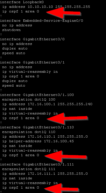
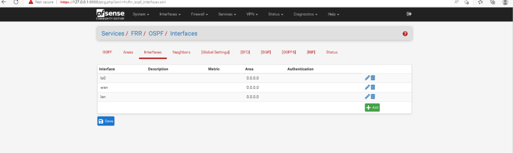
For the second requirement, area numbers must match. In OSPF, routers are configured into “areas.” Area 0 is also called the “backbone area.” In a multi-area OSPF, all routers that are in a different area must connect to a router that is connected to the backbone area or Area 0. Although I will be configuring a single area OSPF, it is best practice to start with area 0. Illustrated in the topology in Figure 1-1, R1, R2, and FW1 are in area 0. In Cisco IOS there are two ways in which you can configure the OSPF area. You can either configure the OSPF area directly on the interface in interface configuration mode or use the network command in OSPF configuration mode. I chose to configure the OSPF area directly on each interface (Figure 1-5). On R1, I need to configure the OSPF area on all the sub interfaces on g0/1 and on the loopback interface(Figure 1-6). To configure an OSPF area in pfsense, you need to select Services>FRR OSPF. Then you need to select the “Areas” tab and then select the add button. The netgate documentation says that in the area field, area should be entered similar to an IP address – 0.0.0.0 (Figure 1-7). To configure the OSPF interfaces in the pfsense console, go to Services>FRR OSPF and then select the Interfaces tab. Then select the interface from the drop down menu and enter 0.0.0.0 in the area field (Figure 1-8). There are some other interface config options to mention here but Ill come back to it.


Note: The OSPF service does not come installed in a default installation of pfsense, you must install this package. You can do this by going to System>Package Manager>Available Packages. Here search for “FRR” and then install the package.
The third requirement is that interfaces running OSPF need to be in the same subnet. This is the requirement that was giving me the most grief and I spent some time making sure that I had end to end connectivity between all my routers. In this topology, all the routers need to be in VLAN 100 and on the 172.16.100.0/28 network. I also went off on a tangent and made sure I would be able to remote manage all the switches in the network by connecting them all to ports in VLAN 100 on S1. I also went off into another tangent and made sure there was end to end connectivity between all my endpoints using static routing before implementing OSPF. This took some time to figure out. There were certain Windows endpoints in LAN 1 and in LAN 2 that were not responding to ICMPv4 echo requests. It winded up being that I needed to enable the rule in the windows defender firewall. I also had to configure the necessary rules on the pfsense firewall so that I may manage it remotely and allow traffic to pass on the LAN side of the firewall. Since this is my lab environment, I chose to use an SSH tunnel. I created a rule to allow inbound SSH traffic on the WAN coming from the pc that I want to manage this pfsense firewall on. Later on Ill delete this rule and use a remote access VPN.
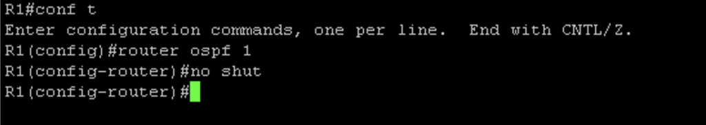
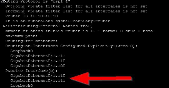
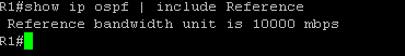
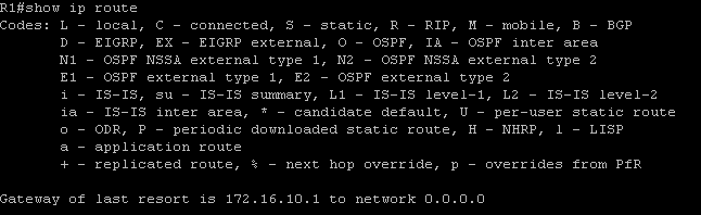
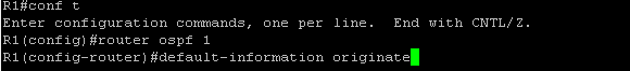
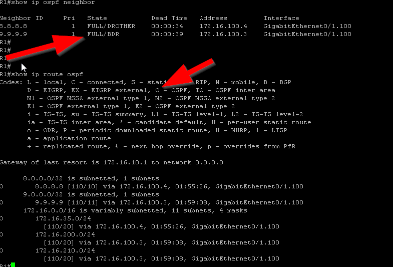
The fourth requirement is making sure that the OSPF process is running on the router. In Cisco IOS, this can be done simply by either creating the OSPF instance or by issuing the #no shut command if there already is an OSPF instance configured on the router that is shutdown(Figure 1-8). While in OSPF configuration mode, I also made some additional configurations. By configuring OSPF on each interface, I told my routers what networks I would like to be advertised. However I don’t want my router sending OSPF messages to interfaces that are not connected to routers. Interfaces that are pointing to a LAN will not respond back to the router with OSPF messages so it is best to prevent the reception and transmission of OSPF messages on those interfaces. In cisco IOS, you can do this with the #passive-interface command in OSPF configuration mode. I did this for all LAN interfaces as well as the loopback interfaces (Figure 1-9 & Figure 1-10). I also made an adjustment to the reference bandwidth which is part of the formula that OSPF uses to calculate the cost of a route. OSPF has a problem with how it calculates the cost of routes in that 100mpbs links and 1000mbps links have an equal cost of 1. The default reference bandwidth on cisco routers is 100mpbs. To calculate the cost of a fast ethernet link, you would divide 100mbps(reference bandwidth) by 100mbps(link speed) to get a cost of 1. If you do this same math for a gigabit link you get a cost of 0.1 which cisco ios just rounds up to 1. This is a problem because this means that OSPF will load balance between these two links and what we really want, is for OSPF to choose the best and fasted route. We can fix this problem by changing the default reference bandwidth to something else using the #auto-cost reference-bandwidth command in OSPF configuration mode(Figure 1-11). We can verify the reference bandwidth by using the #show ip ospf command (Figure 1-12). The last piece of config in OSPF configuration mode I needed to make was to advertise a default route. To advertise a default route to routers running OSPF, you need to first make sure that the default gateway is configured on the router located at the edge of the network. For my topology, that is R1. To advertise a default route, issue the #default-information originate command in OSPF configuration mode (Figure 1-13 & 1-14). Before moving on to enabling OSPF on the pfsense firewall, I wanted to verify that R1 and R2 became OSPF neighbors and are sharing routes. To do this I issued the #show ip ospf neighbors command and the #show ip route ospf command. (Figure 1-15) shows the output of these commands after FW1 becomes an OSPF neighbor) R2 is in the full state and has the backup designated router role. In the #show ip route ospf output only ospf routes are listed. Routes that have the code name “O” are routes learned by OSPF.
Note: It may be necessary to reset the OSPF process all together with the #clear ip ospf in privileged exec mode. This however will clear all OSPF neighbors and erase all routes learned from OSPF and should not be done without careful consideration especially in large networks.


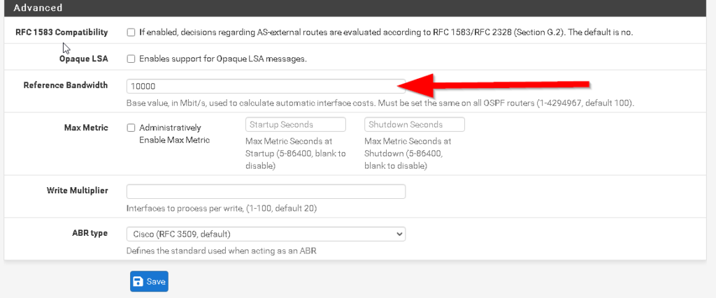
On my pfSense box, enabling the OSPF Process is as simple as checking a box (Figure 1-16). You can do this by going to Services>FRR OSPF and landing on the OSPF tab. Before doing that though, I needed to make the reference bandwidth on FW1 consistent with the cisco routers. If you scroll down in the same tab you will see the advanced section with a field in where you can update the reference bandwidth (Figure 1-17). Additionally I made the LAN interface and loopback interfaces on FW1 passive interfaces. Figure 1-8 shows the OSPF interface configuration page where there is a checkbox labeled “Interface is Passive.” Before enabling OSPF, on pfsense to make it a neighbor I want to make a couple more additional configuration changes on pfsense so that it becomes an OSPF neighbor(although I spoiled that surprise with the previous screenshot).

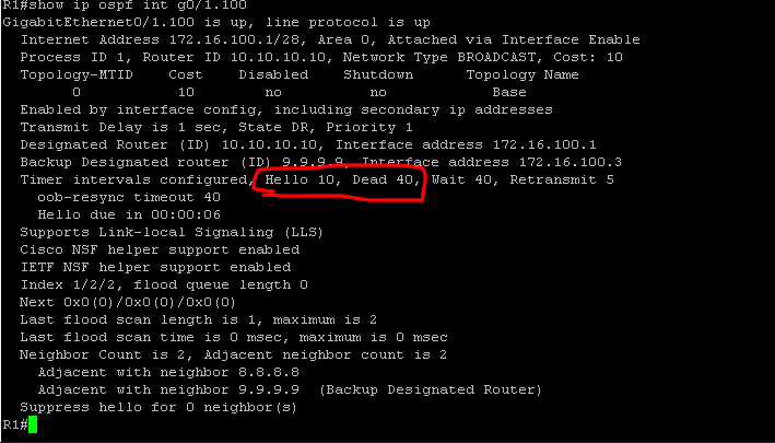
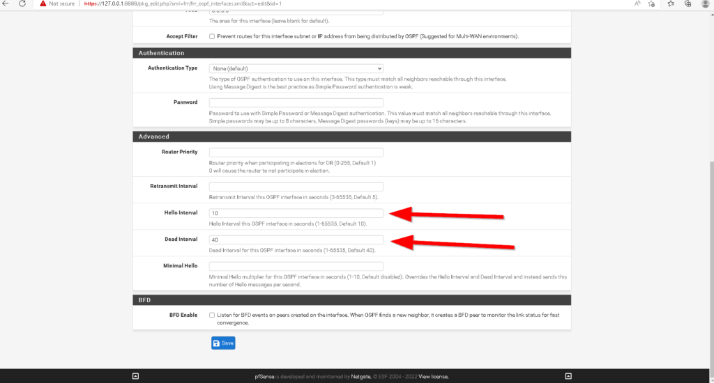
The fifth requirement is that hello and dead timers must match. By default on cisco routers, OSPF sends hello messages every 10 seconds to confirm network adjacency to other OSPF neighbors as well as dynamically discover other routers running OSPF. Also by default, a timer of 40 seconds is reset every time an OSPF hello message is sent. If for some reason an OSPF neighbor does not receive a hello message from an adjacent OSPF neighbor by the time the 40 second dead timer reaches 0, that router is removed as an OSPF neighbor. You can verify the hello and dead times by issuing the #show ip ospf interface command (Figure 1-18). On pfsense the default hello and dead timers are not the same so we must change them. In the Interfaces tab, if you scroll down, you will see the advanced tab where you may configure the hello and dead timers. I did this for each ospf interface (Figure 1-19).
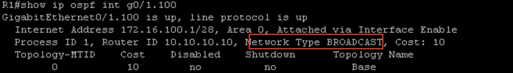
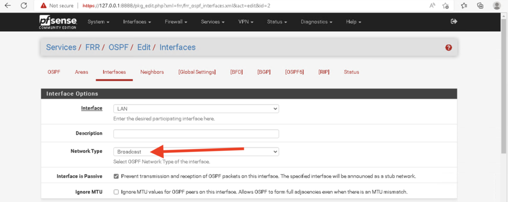
The sixth requirement is that OSPF Network types must match. On Cisco IOS, by default ethernet interfaces are set to the Broadcast Network Type. You can verify the network type on an OSPF interface by issuing the #show ip ospf interface command (Figure 1-20). In pfsense, you have to configure the network type manually in the interfaces tab (Figure 1-21).
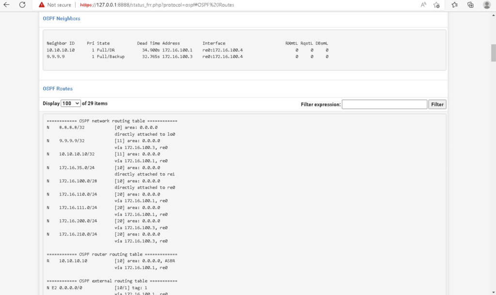
The seventh and eighth requirements are that authentication settings need to match and IP MTU settings need to match. I wont be requiring OSPF neighbors to be authenticating and I have not made any changes to MTU values. After enabling OSPF in pfsense, you can check the neighbor status and the routes learned from OSPF in the Status tab. Finally, I connected a laptop to S3 and tested connectivity with ping to every endpoint successfully!