Why Inter-VLAN Routing?
VLANs or Virtual Local Area Networks are awesome. They allow you to essentially break up one physical LAN into multiple logical or virtual LANs. When you create a VLAN on a Cisco switch and assign an interface to that VLAN, all hosts in the same VLAN are able to communicate with each other. But what happens when a host on one VLAN needs to communicate with a host on a totally separate VLAN?
That is where Inter-VLAN routing picks up the tab. In order for hosts on different VLANs to communicate with each other you need a router or a Layer 3 device. Communication between hosts in the same VLAN lives within Layer 2 but communication between hosts on different VLANs lives within Layer 3.
You can configure Inter-VLAN routing a few different ways on a Cisco router. For this network, I will be using a configuration method known as Router-on-a-stick. ROAS is just a simple way to describe how routing occurs between VLANs. Wendell Odom’s CCNA book describes this best. In a ROAS configuration, “routers route packets to subnets associated with VLANs connected to a router 802.1q trunk.
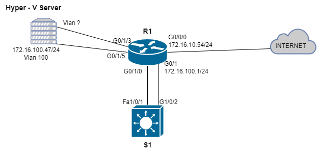
Here is a network diagram of the topology:
The Hardware
The end hosts will live in my Hyper-V Server. Im running Windows Server 2019 on a Dell Optiplex 7010 with the Hyper-V server role installed. Some specifications to note about this machine is that there are two SSDs in a RAID 0 for a total of 256GB of storage, 32GBs of DDR3 and 3 Gigabit NICs (1 onboard, 2 USB). R1 is a Cisco 1941 Series ISR Gen 2 router with two additional modules: A 1 gigabit L3 Port and an 8 Port Gigabit L2 Switch. S1 is a Cisco Catalyst 3750v2. S1 is a multi-layer switch however in this topology it is functioning as a L2 device.
Describing the current Topology
Currently what is setup is a flat network. All the switch ports on R1 are in Vlan 100. Fa1/0/1 and G0/1/2 on S1 are access ports in VLAN 100. The Hyper V Server is connected to a switch port assigned to VLAN 100 on R1. Something to note at this point is that in order for routing between hosts on different VLANs to occur on R1’s L2 switch, I needed to connect an additional switch (S1) to the L2 switch on R1 and create trunks. Finally, R1 is configured as a DHCP client on it’s G0/0/0 interface. The WAN IP on R1 is a private IP address because this is a testing environment.
My Requirements
- A separate network for VMs
- The VMs in the newly created network should be able to reach the network that the Hyper-V host is connected to
- The Hyper-V Host and guests should be able to reach the internet
Configuration
As previously mentioned in order to configure Inter-VLAN routing in this network, I need to configure ROAS on R1. Trunks will need to be configured on R1’s G0/1 and G0/1/0 interface. I will create VLAN 110 on R1 and S1 as well as assign it a subnet. This VLAN will be used to provide connectivity to the end hosts. I will assign VLAN 110 to R1’s G0/1/3 switchport. I also need to configure trunks on S1’s G1/0/2 and Fa1/0/1.
In the Hyper-V Console, I must create an external switch and assign it to the USB NIC that is connected to the host. Currently I have two VMs – a couple Server 2019 VMs. I will assign one VM to a vSwitch that will pass untagged traffic in VLAN 100 and the other VM to a vSwitch that will pass untagged traffic in VLAN 110.
Finally, I want my VMs to be able to reach the internet, so I also will have to reconfigure the access list and the NAT statement on R1. After all of this I will test connectivity between my VLANs and the network my host is connected to.
R1
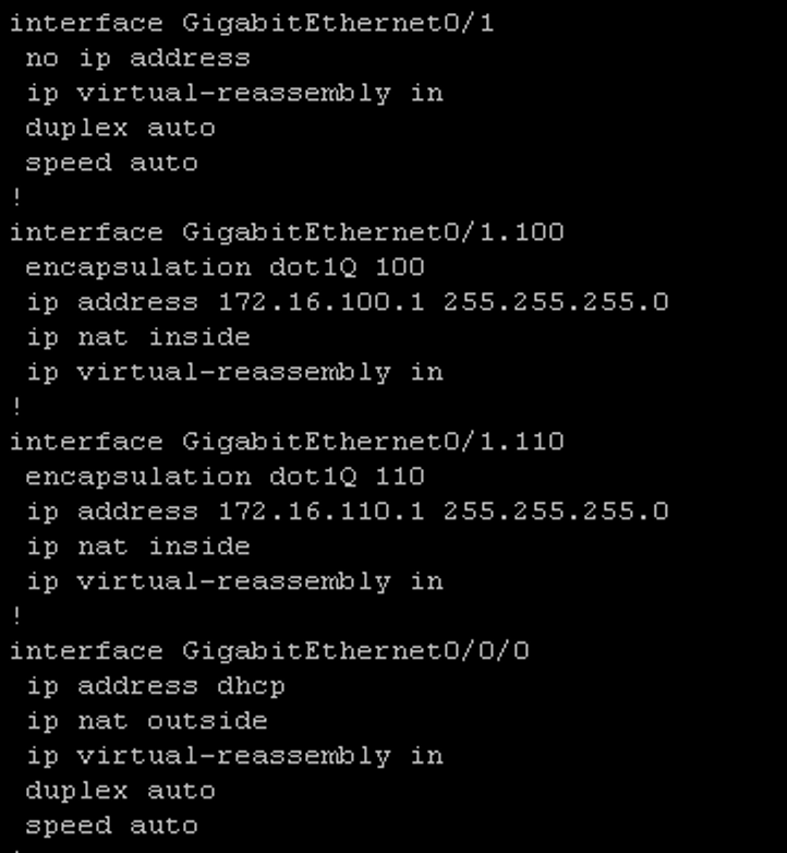
On R1 I needed to enter interface configuration mode on g0/1 and remove the ip address:
#no ip address
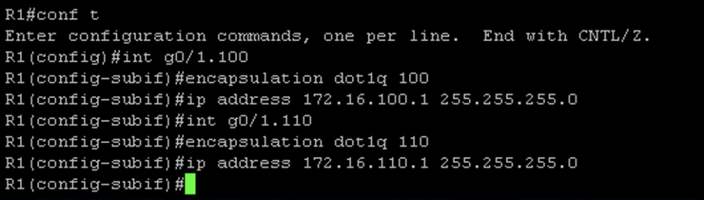
To configure ROAS, you need to create sub interfaces and configure the encapsulation protocol. I also configured an IP address on each sub interface
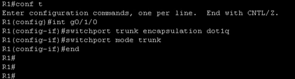
Next I needed to configure the switch module on R1. On the g0/1/0 switchport I needed to remove access to vlan 100 and remove the existing Access Port configuration:
#no switchport mode access
#no switchport access vlan 100
To configure the trunk I issued the following commands:
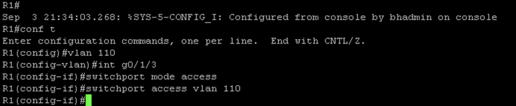
Next I needed to remove access to vlan 100 from the g0/1/3 interface with the command #no switchport access vlan 100. Then I created vlan 110 and assigned int g0/1/3 to vlan 110:
S1 Configuration
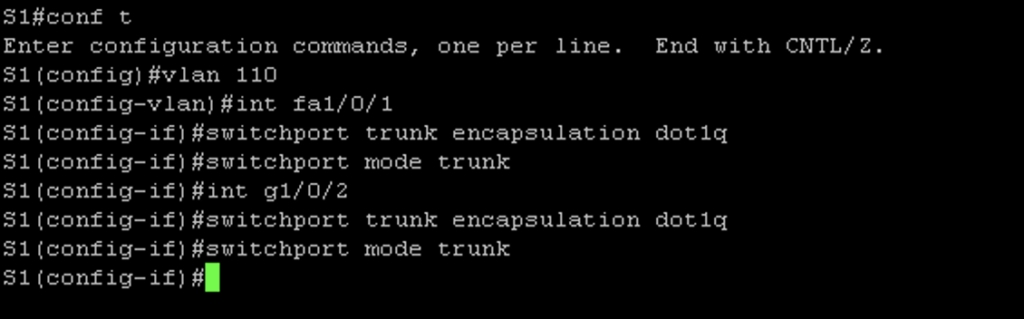
On the switch I needed to remove the existing Access port configuration and remove access to vlan 100 with the following commands on int fa1/0/1 and g1/0/2:
#no switchport mode access
#no switchport access vlan 100
Then I issued the following commands to configure the trunks on S1’s fa1/0/1 and g1/0/2 interfaces:
Hyper-V Configuration
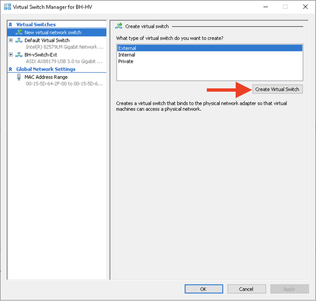
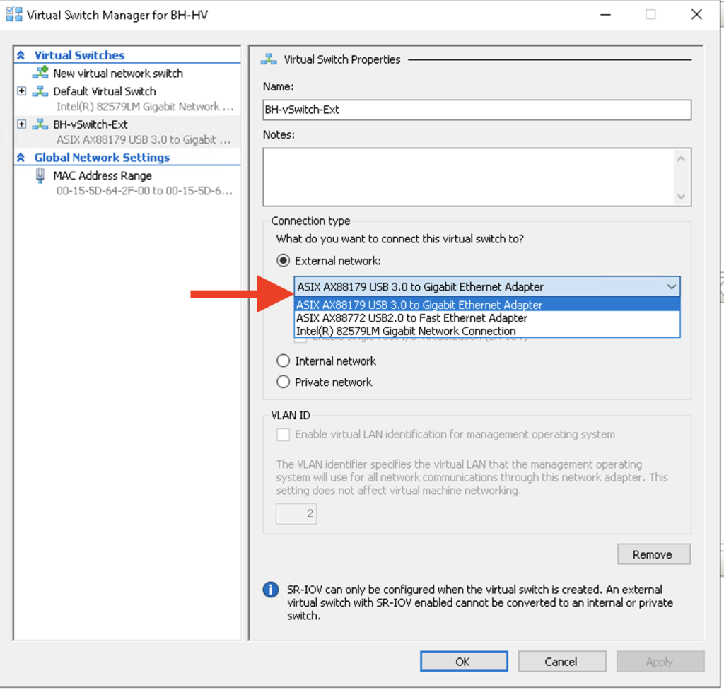
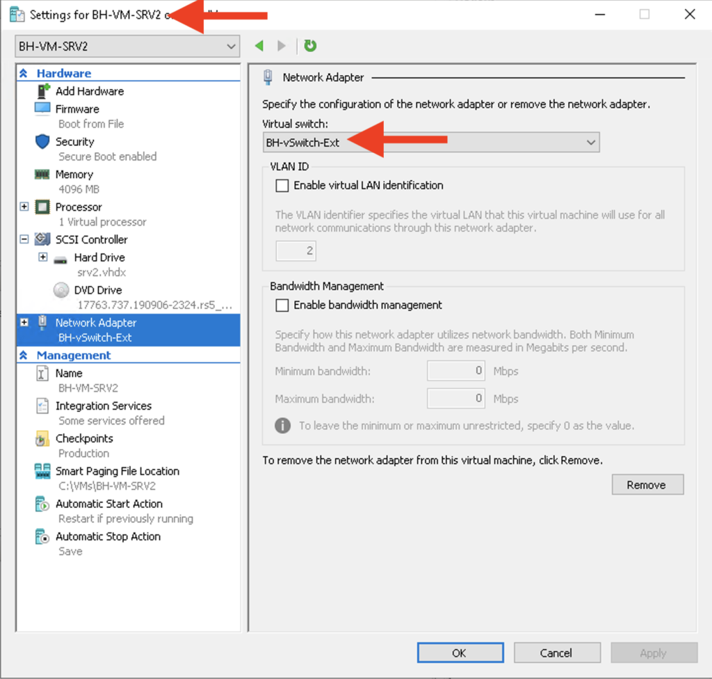
First I created an external switch. I want an external switch because I want the ability for my VMs to communicate with the host. At some point I will make one of these VMs a domain controller and I want to join the host to the domain for central management. Creating a switch in Hyper-V is pretty trivial; just select the Virtual Switch Manager and then select “Create Virtual Switch” Then, I assigned the USB NIC to the new vSwitch:
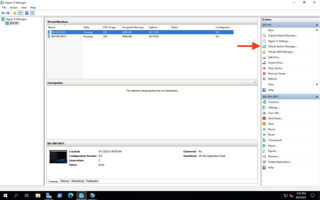
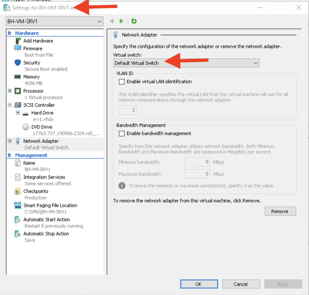
Last thing to do in the Hyper-V Console is to connect these VMs to a vSwitch. I will connect BH-VM-SRV1 to “Default Virtual Switch” and I will assign BH-VM-SRV2 to BH-vSwitch-Ext. Each vSwitch will pass untagged VLAN traffic in different VLANS but they will be able to communicate with each other.
Configuring NAT
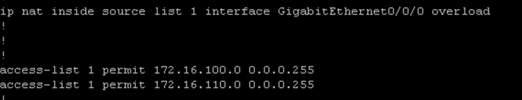
Initially when I was planning all this out I forgot all about NAT! I did some pings to Google’s DNS servers and they failed. It was because I needed to add an entry to the access list on R1 to allow traffic from VLAN 110’s subnet. I also needed to issue the #ip nat inside command while in interface configuration mode for g0/1.110. This command will allow hosts in the 172.16.110.0/24 subnet to access the internet. In addition this command also tells the router that these IPs are not seen outside of the router. Alternatively, the #ip nat outside command tells the router that the IPs on that interface (in the case of R1 interface g0/0/0) should be known outside of the router:
Last thing to do to ensure NAT works correctly is to add an entry to the existing access list (ACL) to allow the traffic. In Cisco IOS I can use ACLs in my NAT statement to identify the inside local addresses that I would like to apply NAT to:
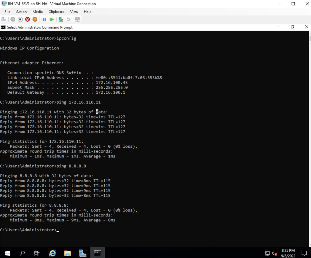
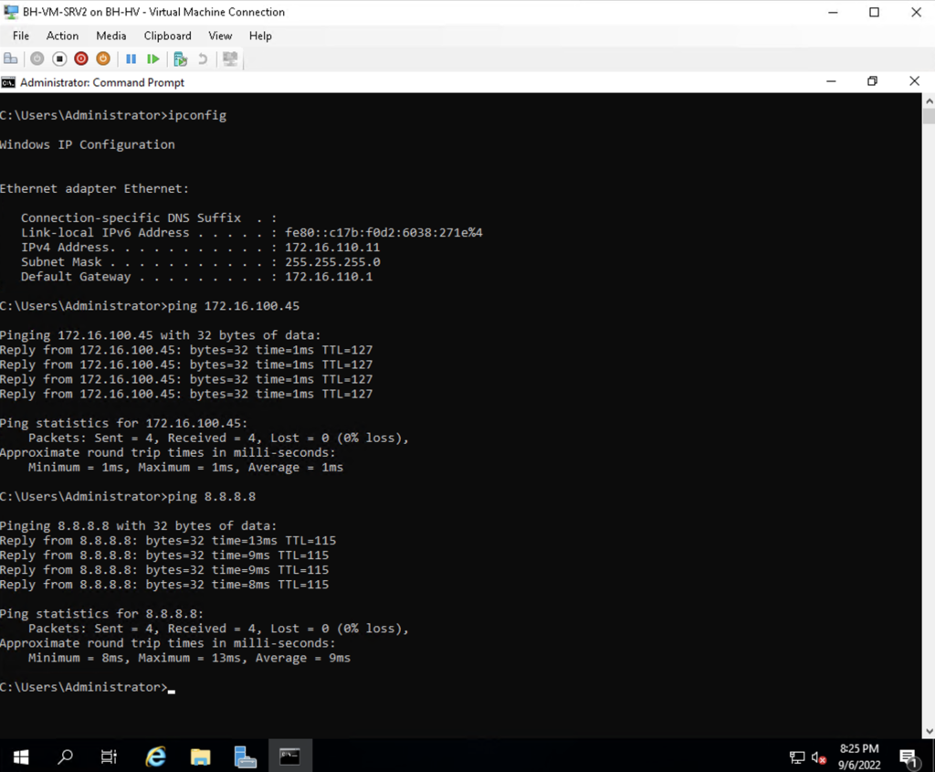
Testing Connectivity
I 100% had to do some tinkering to make sure everything was working but everything works as I intended! Below are two screenshots identifying the IP address of each VM with the ipconfig command and then successful pings to each VM and Google’s DNS server 8.8.8.8:
Security Considerations
One thing I could have done to make this configuration more secure is to lock down the VLANs that are allowed on the trunks. Currently the way I configured the trunks, all VLANs are allowed on the trunks, even the default VLAN.